")
 (1)")
 (1)")
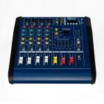
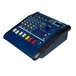
Description
| Microphone Input | Balance X2R socket to receive various low level microphone signals |
| Line Input | Non- balanced socket,receiving various unbalanced or balanced high level voice tip signals. |
| Channel Peak Display | When the channel signal is clipped due to too high lift, the indicator lights up to prompt DJ to make adjustmeny |
| Gain Control | Adjust this knob to increase or decrease channel level from -60db to -16db |
| Channel Signal Switch | Press this key to attenuate the channel signal by 20dB. |
| Treble Control | Adjust the knob to control channel treble tone. |
| If Tone Control | Adjust the knob to control the channel midrange tone. |
| Bass Control | Adjust the knob to control the channel bass tone |
| Auxiliary Knob | Ajust the auxiliary knob to enter the specified equipment as required for the channel signal,without affecting the mixed amplification signal. |
| Insert Adjustment For Internal Effect |
Adjust the knob to allow the channel signal to enter the effector. |
| Balance Control | Adjust knob , can make the left , in the channel distribution as required , make it toldeal stereo effect. |
| Channel Montoring switch |
Press this button, the channel can be monitored by headphones. |
| Channel Volume Attenuation Driver |
Adjust the push, can control the channel signal size, to match the overall performance. |
| Main Output Section | |
| Output status display | It can be used to display the main channel out put directly and make the adjustment reach the ideal state |
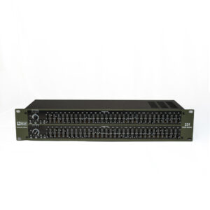
| Internal Balance | The equilizer can adjust each frequency band according to the needs in order to achieve ideal syllables. |
| Stereo main sound Attenuation promoter |
By adjusting the driver, you can make the main output level meet the ideal requirement state. |
| Internal Effect Monitoring Section |
|
| Recording OutPUT Knob | Adjust the knob, you can adjust the size of recording signal as needed, to the ideal state. |
| Auxiliary Send Level Adjustment | The level of the control auxiliary send is turned off to the interface of the external calling device. |
| Auxiliary Return Level Regulation | Control the return level of the external signal, and reach the ideal state of the mixing of the generator signal and main channel signal. |
| Signal Adjustment For Internal Effect | Adjust the knob so that the input signal can be added to the effector as required. |
| Digital Effect Display | Adjust UP and DOWN buttons to achieve ideal reverb effect state according to your needs. This function displays 16 levels effect state for adjustment. |
| Loop Back Adjustment Of Internal Effect | By adjusting the knob, the loop signal of the internal effect can reach the ideal state. |
| Internal Effect Balance Control | Adjust the knob, can make the effect in the machine according to the requirments of distribution, into the left , right sound channel. |
| Internal Effect Monitoring Switch | Press the button to use the effect signal in the earphone monitor. |
| In Machine Effect Attenuation Push | By adjusting the driver , you can control the output level of the effect signal. |
| Headphone Monitor Volume Adjustment | By adjusting the knob, the volume of the head phone can be adjusted. |
| Headphone Socket | Stereo headphone connection jack can monitor the output of stereo, mono, marshalling and first output channel. |
| Bluetooth | Bluetooth receiver |
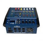
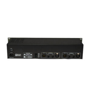
| Rear Panel | |
| power switch | |
| Speaker Out | 4 speaker outs 2 mono and 2 speakon outs |
| PMS-4BLT USB | Channel |
|
|
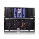
| Power RMS WATTS | 200Wx2=400W | ||
| Power pmpo watts | 500WX2=1000W | ||
| Total Harmonic Distortion |
0.1% below (1KHX Full Power) | ||
| Power Requirements | AC 220/50Hz or 120V/60Hz | ||
| Impedance | 8Ω |
More Products From This Vendor
More Products-
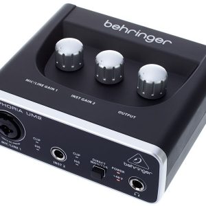
UM2 Behringer U-PHORIA Audio Interface
250.00AED399.00AED -


Behringer HPX6000 Professional DJ Headphones
240.00AED265.00AED -
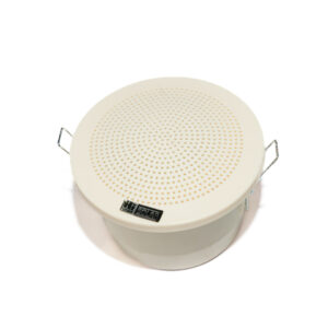

T-629
40.00AED50.00AED -

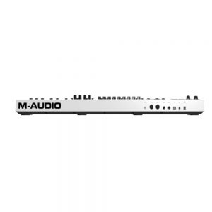
Code 49 USB MIDI Controller with X/Y Pad
1,019.00AED1,100.00AED -
AKG P120 Large-diaphragm Condenser Microphone
489.00AED605.00AED -
M-Audio Oxygen 61 MKV USB MIDI Controller
828.00AED1,059.00AED -

Universal Audio Apollo Twin X DUO Heritage Edition (Desktop/Mac/TB3)
4,200.00AED4,900.00AED -

Fifine k669B Metal Condenser Recording Microphone
200.00AED250.00AED -
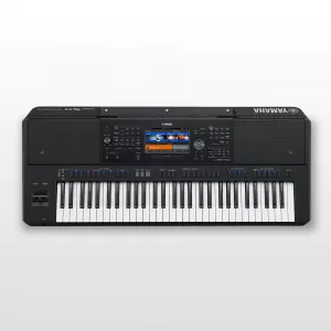
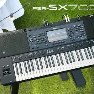
PSRSX-700
4,800.00AED5,000.00AED -
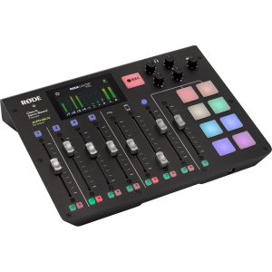
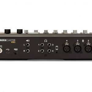
RODECaster Pro Podcast Studio RCP-Mixer
2,900.00AED2,999.00AED
Related products
More Products-

234XL
350.00AED400.00AED -

SH-200
100.00AED150.00AED -
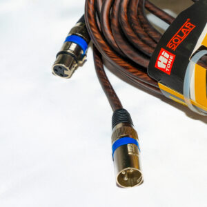
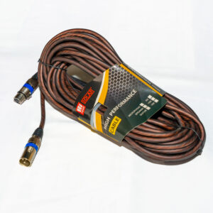
XLR M/F-15MTR
120.00AED200.00AED -
EQ-231
350.00AED400.00AED